|
|
|
PDF AS1100 Data sheet ( Hoja de datos )
| Número de pieza | AS1100 | |
| Descripción | Serially Interfaced 8-Digit LED Driver | |
| Fabricantes | AMSCO | |
| Logotipo | ||
Hay una vista previa y un enlace de descarga de AS1100 (archivo pdf) en la parte inferior de esta página. Total 12 Páginas | ||
|
No Preview Available !
www.DataSheet4U.com
Data Sheet AS1100
Serially Interfaced, 8-Digit LED Driver
AS1100
DATA SHEET
Key Features
- 10MHz Serial Interface
- Individual LED Segment Control
- Decode/No-Decode Digit Selection
- 20µA Low-Power Shutdown (Data Retained)
- Extremely low Operating Current 0.5mA in open loop
- Digital and Analog Brightness Control
- Display Blanked on Power-Up
- Drive Common-Cathode LED Display
- Software Reset1
- Optional External clock
- 24-Pin DIP and SO Packages
- Fully compatible to MAX7219
Every individual segment can be addressed and updated
separately. Only one external resistor is required to set the
current through the LED display. Brightness can be
controlled either in an analog or digital way. The user can
choose the internal code-B decoder to display numeric
digits or to address each segment directly. The AS1100
features an extremely low shutdown current of only 20µA.
and an operational current of less than 500µA. The number
of visible digits can be programmed as well. The AS1100
can be reset by software and an external clock can be used.
Several test modes support easy debugging.
The AS1100 is fully compatible to the MAX 7219. AS1100 is
offered in a 24 pins PDIP and SOIC package.
General Description
Applications
- Bar-Graph Displays
The AS1100 is an LED driver for 7 segment numeric
- Industrial Controllers
displays of up to 8 digits. The AS1100 can be programmed
- Panel Meters
via a conventional 4 wire serial interface. It includes a BCD
- LED Matrix Displays
code-B decoder, a multiplex scan circuitry, segment and
- White Goods
display drivers and a 64 Bit memory. The memoryDisatuasSedhetoet4U.com
store the LED settings, so that continuous reprogramming is
not necessary.
DataShee
TOP
DIN 1
DIG0 2
DIG4 3
GND 4
DIG6 5
DIG2 6
DIG3 7
DIG7 8
GND 9
DIG5 10
DIG1 11
LOAD 12
24 DOUT
23 SEG D
22 SEG DP
21 SEG E
20 SEG C
19 VDD
AS1100 18 ISET
17 SEG G
16 SEG B
15 SEG F
14 SEG A
13 CLK
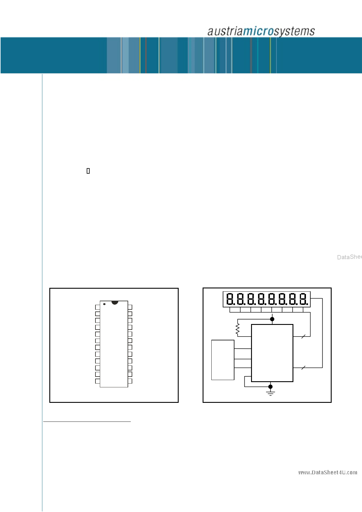
DIP/SO 24
Pin Configuration
1 Software Reset and external clock are not supported by
MAX7219
9.53k
MOSI
µP I/O
SCK
+5V
19
VDD
18 ISET DIG0-DIG7
1 DIN
8 Digits
12 LOAD
1
9
CLK
SEG A-G
SEP DP
GND GND
8 Segments
4
8-Digit µP Display
Typical Application Circuit
DataSheet4U.com
Revision 1.32, Oct. 2004
DataSheet4 U.com
Page 1 of 12
1 page 
www.DataSheet4U.com
Data Sheet AS1100
et4U.com
Decode-Mode Register
used. To avoid differences in brightness the scan limit
In the AS1100 a BCD decoder is included. Every digit can
register should not be used to blank portions of the display
be selected via register 09h to be decoded. The BCD code
(leading zeros).
consists of the numbers 0-9, E,H, L,P and -. In register 09h
a logic high enables the decoder for the appropriate digit. In
case that the decoder is bypassed (logic low) the data Bits
Register
Address
Hex
D15–D12 D11 D10 D9 D8 Code
D7-D0 correspond to the segment lines of the AS1100. In
table 4 some possible settings for register 09h are shown.
Bit D7, which corresponds to the decimal point, is not
affected by the settings of the decoder. Logic high means
that the decimal point is displayed. In table 5 the font of the
Code B decoder is shown. In table 6 the correspondence of
the register to the appropriate segments of a 7 segment
display is shown (see figure 2)
No-Op
Digit 0
Digit 1
Digit 2
Digit 3
Digit 4
Digit 5
Digit 6
X 0 0 0 0 0xX0
X 0 0 0 1 0xX1
X 0 0 1 0 0xX2
X 0 0 1 1 0xX3
X 0 1 0 0 0xX4
X 0 1 0 1 0xX5
X 0 1 1 0 0xX6
X 0 1 1 1 0xX7
Digit 7
Intensity Control and Interdigit Blanking
Brightness of the display can be controlled in an analog way
by changing the external resistor (RSET). The current, which
flows between VDD and ISET, defines the current that flows
through the LEDs. The LED current is 100 times the ISET
current. The minimum value of RSET should be 9.53kΩ,
which corresponds to 40mA segment current. The
Decode
Mode
Intensity
Scan Limit
Shutdown
Not used
brightness of the display can also be controlled digitally via
Reset and
register 0Ah. The brightness can be programmed in 16
ext. Clock
steps and is shown in table 7. An internal pulse width
Display
modulator controls the intensity of the display. DataSheet4U.coTmest
X
X
X
X
X
X
X
X
1
1
1
1
1
1
1
1
Table 2: Register address map
0 0 0 0xX8
0 0 1 0xX9
0 1 0 0xXA
0 1 1 0xXB
1 0 0 0xXC
1 0 1 0xXD
1 1 0 0xXE
1 1 1 0xXF
DataShee
Scan-Limit Register
The scan limit register 0Bh selects the number of digits
displayed. When all 8 digits are displayed the update
frequency is typically 800Hz. If the number of digits
displayed is reduced, the update frequency is reduced as
well. The frequency can be calculated using 8fOSC/N,
where N is the number of digits. Since the number of
displayed digits influences the brightness, the resistor RSET
Mode
Shutdown
Mode
Normal
Operation
Address Code
Register Data
(Hex) D7 D6 D5 D4 D3 D2 D1 D0
0xXC
XXXXXXX0
0xXC
XXXXXXX1
should be adjusted accordingly. Table 9 shows the
Table 3: Shutdown register format (address (hex) = 0xXC)
maximum allowed current, when fewer than 4 digits are
DataSheet4U.com
Revision 1.32, Oct. 2004
DataSheet4 U.com
Page 5 of 12
5 Page 
www.DataSheet4U.com
Data Sheet AS1100
Inches Millimeters
Dim Min Max Min Max
A --- 0.180 --- 4.572
A1 0.015 --- 0.380 ---
A2 0.125 .0175 3.180 4.450
A3 0.055 0.080 1.400 2.030
B 0.015 0.022 0.381 0.560
B1 0.045 0.065 1.140 1.650
C 0.008 0.014 0.200 0.355
D 1.140 1.265 28.96 32.13
D1 0.005 0.080 0.130 2.030
E 0.300 0.325 7.620 8.260
E1 0.240 0.310 6.100 7.870
e 0.100 BSC 2.54 BSC.
eA 0.300 BSC 7.62 BSC.
eB 0.400 BSC 10.2 BSC.
L 0.115 0.150 2.921 3.810
Figure 5: PDIP-24 package dimensions
et4U.com
Segment Driver Capability, VDD = 5V, Logic Level = High
50 DataSheet4U.com
Upper Limit
45
40
35
Lower Limit
30
25
20
15
10
5
0
0 0.5 1 1.5 2 2.5 3 3.5 4 4.5
Voltage below VDD at output in V
Figure 6: Segment driver capability
DataShee
DataSheet4U.com
Revision 1.32, Oct. 2004
DataSheet4 U .com
Page 11 of 12
11 Page | ||
| Páginas | Total 12 Páginas | |
| PDF Descargar | [ Datasheet AS1100.PDF ] | |
Hoja de datos destacado
| Número de pieza | Descripción | Fabricantes |
| AS1100 | Serially Interfaced 8-Digit LED Driver | AMSCO |
| AS1101 | (AS1101 - AS1104) Low-Dropout LED Drivers | AMSCO |
| AS1102 | (AS1101 - AS1104) Low-Dropout LED Drivers | AMSCO |
| AS1103 | (AS1101 - AS1104) Low-Dropout LED Drivers | AMSCO |
| Número de pieza | Descripción | Fabricantes |
| SLA6805M | High Voltage 3 phase Motor Driver IC. |
Sanken |
| SDC1742 | 12- and 14-Bit Hybrid Synchro / Resolver-to-Digital Converters. |
Analog Devices |
|
DataSheet.es es una pagina web que funciona como un repositorio de manuales o hoja de datos de muchos de los productos más populares, |
| DataSheet.es | 2020 | Privacy Policy | Contacto | Buscar |