|
|
|
PDF LZC811 Data sheet ( Hoja de datos )
| Número de pieza | LZC811 | |
| Descripción | PSR & PFC LED Driver Controller | |
| Fabricantes | LOZEN TECHNOLOGY | |
| Logotipo | ||
Hay una vista previa y un enlace de descarga de LZC811 (archivo pdf) en la parte inferior de esta página. Total 9 Páginas | ||
|
No Preview Available !
LZC811
PSR & PFC LED Driver Controller
General Description
Fly-back topology
The LZC811 is a single-power stage, • Real-Current control to meet accurate
isolated and primary side offline LED lighting
output current
regulator which achieves high power factor. • Very less components
The proprietary real-current control method • Programmable input AC voltage
can control the LED current accurately from
compensation
the primary side information. It can • Leading Edge Blanking on CS/FB pin
significantly simplify the LED lighting system • Protection Features
design by eliminating the secondary side
Building in hysteresis OTP
feedback components and the opto-coupler.
VDD over voltage protection
The LZC811 integrates active power factor
Cycle by cycle current limiting on CS
correction and works in Quasi Resonance
pin
mode (QRM) in order to reduce the
Secondary peak current protection
MOSFET switching losses. With a building in
on CS pin
700V start-up MOSFET, IC can eliminate the
Output short to GND protection
power loss caused by start-up resistors to
Output programmable over voltage
provide a high efficiency solution for lighting
protection
applications. The external programmable
FB and CS pins default protection
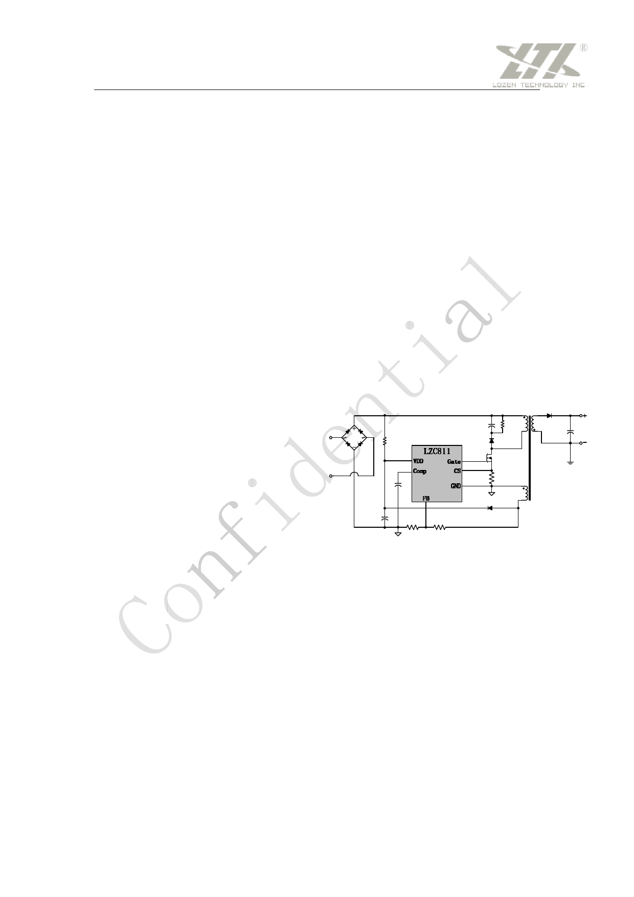
line voltage compensation provides a more Application circuit
precise output current throughout the
universal AC input voltage range. The
leading edge blanking circuit on the CS/FB
input removes the signal glitch and results in
reduced external components and system
cost. The multi-protection features of
LZC811
VDD Gate
Comp CS
GND
FB
LZC811 greatly enhance the system
reliability and safety. The LZC811 features
VDD and output over voltage protection;
Fig 1 Application Circuit
output short circuit protection, cycle-by-cycle
current limit and secondary peak current
protection on CS pin, VDD UVLO and
auto-restart and over-temperature protection.
The driver output voltage is clamped at 18V
to protect the external power MOSFET.
Features
• Single stage PFC
• Primary side regulation without
Secondary Feedback
• Quasi Resonance (QR) mode with
Confidential
Page 1
Preliminary Ver:0.24
1 page 
LZC811
PSR & PFC LED Driver Controller
Operation
The LZC811 is a primary side control offline LED controller that incorporates all the features for high
performance LED lighting. LED current can be accurately controlled with the real current control
method form the primary side information. Active Power Factor Correction (PFC) is included to
eliminate the unwanted harmonic noise injected onto the AC line.
Startup
During start-up, the current can charge up the VDD hold capacitor. the turn-on and turn-off thresholds
of LZC811 are approximately 15V and 9V respectively.. The 6V hysteresis voltage is implemented to
prevent shutdown from a voltage dip during start-up.
Quasi Resonance mode (QRM)
During the external power MOSFET on time (TON), the rectified input voltage is applied across the
primary side inductor (Lm) and the primary current increases linearly from zero to the peak value (IPK).
When the external power MOSFET turns off, the energy stored in the inductor forces the secondary
side diode to be turn-on, and the current of the inductor begins to decrease linearly from the peak
value to zero. When the current decreases to zero, the parasitic resonant of inductor and all the
parasitic capacitance makes the power MOSFET drain-source voltage decrease, this decreasing is
also reflected on the auxiliary winding. The zero-current detector in FB pin generates the turn on
signal of the external MOSFET when the FB voltage is lower than 0.2V and ensures the MOSFET turn
on at a valley voltage .
As a result, there are virtually no primary switch turn-on losses and no secondary diode
reverse-recover losses. It ensures high efficiency and low EMI noise.
Active Power Factor Correction (APFC)
LZC811 is designed with quasi-resonance and constant on time Ton to achieve high power factor
under normal operation. The on time of LZC811 vary with input AC voltage VP Sinϖt and load
condition and its value is constant basically because of very large loop compensation capacitance on
CMP pin. According to following equations,
I L − peak
=
VP
Sinϖt
Lm
×
Ton
I L−avg
=
VP Sinϖt
2× Lm
×
Ton
2
×
f osc
The peak current I L− peak and average current I L−avg of transformer will be shaped as AC input
sinusoid too because Ton and fosc both are constant and then high power factor can be achieved.
Confidential
Page 5
Preliminary Ver:0.24
5 Page | ||
| Páginas | Total 9 Páginas | |
| PDF Descargar | [ Datasheet LZC811.PDF ] | |
Hoja de datos destacado
| Número de pieza | Descripción | Fabricantes |
| LZC811 | PSR & PFC LED Driver Controller | LOZEN TECHNOLOGY |
| Número de pieza | Descripción | Fabricantes |
| SLA6805M | High Voltage 3 phase Motor Driver IC. |
Sanken |
| SDC1742 | 12- and 14-Bit Hybrid Synchro / Resolver-to-Digital Converters. |
Analog Devices |
|
DataSheet.es es una pagina web que funciona como un repositorio de manuales o hoja de datos de muchos de los productos más populares, |
| DataSheet.es | 2020 | Privacy Policy | Contacto | Buscar |